Getting Started Guide: Mapping 2D Drawings to 3D Models
Background
The Models tool in Procore BIM bridges the gap between complex 3D coordination and practical field execution. While 3D models provide a comprehensive view of a project's spatial requirements, field teams often rely on familiar 2D Drawings for precise navigation, layout, and installation.
By mapping 2D drawings directly onto a 3D model, Virtual Design and Construction (VDC) teams create a "best of both worlds" experience. This integration allows users on the Procore Mobile app to view their real-time location on a 2D floor plan while simultaneously seeing the corresponding 3D elements around them. This process, often referred to as 2D Mapping, ensures that coordinated models are not just office assets but are functional tools for quality control and site verification.
Why Use 2D Views?
Enhanced Navigation: Field teams can jump to specific rooms or levels by selecting them on a 2D sheet, which automatically orients the 3D camera to that location.
Precision and Context: Aligning 2D drawings with 3D geometry ensures that the "paper" design matches the coordinated "digital" build, reducing the risk of installation errors.
On-Site Orientation: When combined with Exported Grids from Revit®, mobile users gain a clear sense of their physical coordinates relative to the building’s structural grid lines.
Workflow Continuity: This guide outlines the transition from a Navisworks® coordination environment to a mobile-ready field tool, ensuring that the BIM Lead's work is accessible to the entire project team.
Things to Consider
Prerequisites:
Procore: The Models tool must be active on the project.
Mobile: Install or update the Procore Mobile app (iOS) on your mobile device. You can download it from the Apple App Store.
Windows® Desktop: See What are the hardware and software specifications for viewing models?
Software:
Requires a supported version of Autodesk® Navisworks® (Manage or Simulate) or Revit®.
Requires you to Download and Install the Procore BIM Plugin.
Additional Information:
Only one (1) set of grids can be exported per published model.
The 2D View icon in the mobile viewer will NOT show if no grids are associated with the model. If there are grids, the 2D view option will show when the wall object is selected in the Models tool.
Gridlines can be turned on or off by tool Admins in the Settings area of the mobile viewer. See Settings: Models (iOS).
Steps
Using the Procore BIM Plugin you can transition your models from your desktop environment to Procore for viewing by your field team. This ensures that complex 3D geometry is accessible on the Procore Mobile app and aligned with the corresponding 2D drawings and structural grids.
Publish Navisworks® Models to Procore Using the Procore BIM Plugin
The first step is to publish your new Autodesk® Navisworks® model (or Publish a New Version of a Model) to Procore, configure the navigation viewpoints, and map reference points to create a unified, mobile-ready source of truth for your project team. For the full tutorial, see Publish Navisworks® Models to Procore Using the Procore BIM Plugin.
To learn how, click Show / Hide Steps
Set Up Model Info & Preferences
Open your model in Navisworks®.
Click the Procore tab to use the Procore BIM Plugin.
Click Publish to open the Models window.
In the Models window, choose one option:
Publish a new model: Click New Model.
Publish new version of an existing model: Hover over the model in the list and click Publish Version.
Enter information about the model as follows:
For a new model: Enter the Model Name.
For an existing model: Keep the existing name.
Select the model's Status from the list:
Coordination: For reference only. Not approved for construction.
Construction: Fully coordinated and approved for field installation and layout.
As-Built: Updated to reflect final, field-verified conditions.
Select the Automatic Revisions box to automatically publish a new revision when a new version is updated.
Set your 2D mapping:
Map Drawings: Click Next. This is a required step.
Publish: Click Save Changes.
Configure Model Views & Viewpoints
Set the Home Viewpoint. This is the model's default starting view and thumbnail image. For best results and easy navigation, choose a clear, general overview of the project.
Set the initial viewpoint:
In the viewer, navigate the model to your desired starting position.
Click Add.
Click Save to confirm.
Optional: Update an existing viewpoint:
Navigate the model to the new position.
Click Edit.
Click Save to apply the changes.
Optional: Add or remove any saved views from Navisworks® to make them available in Procore:
Add a saved view:
Click Add.
Mark the checkbox next to each view you want to upload.
Click Add to confirm your selections.
Optional: Remove a saved view:
Click the delete (x) icon next to the viewpoint.
Add & Align 2D Drawings
Add a 2D Sheet:
On the Map Drawings to Model screen, make a selection from the dropdown menu for each of the following required fields:
Level. Select a location level from the drop-down menu.
Drawing Area. Select a drawing area from the drop-down menu.
Drawings. Select the relevant drawing(s).
Click Next.
Map the 2D Sheet to the Model to align aligns the 2D drawing with the 3D model with reference points.
Select reference points on the 3D model:
Click Map Model to begin.
Select two reference points on the 3D model. The points will be labeled 'A' and 'B'.
To clear the selected points, click Reset All.
When satisfied with the points, click Save.
Select matching points on the 2D drawing(s):
Click Map Drawings to begin selecting points on the drawing(s).
Select the same two reference points on the 2D drawing that correspond to points 'A' and 'B' from the model.
The rest of the selected drawings will be automatically mapped
Note: Reference points are saved automatically, but reviewing the drawing turns the checkmark blue.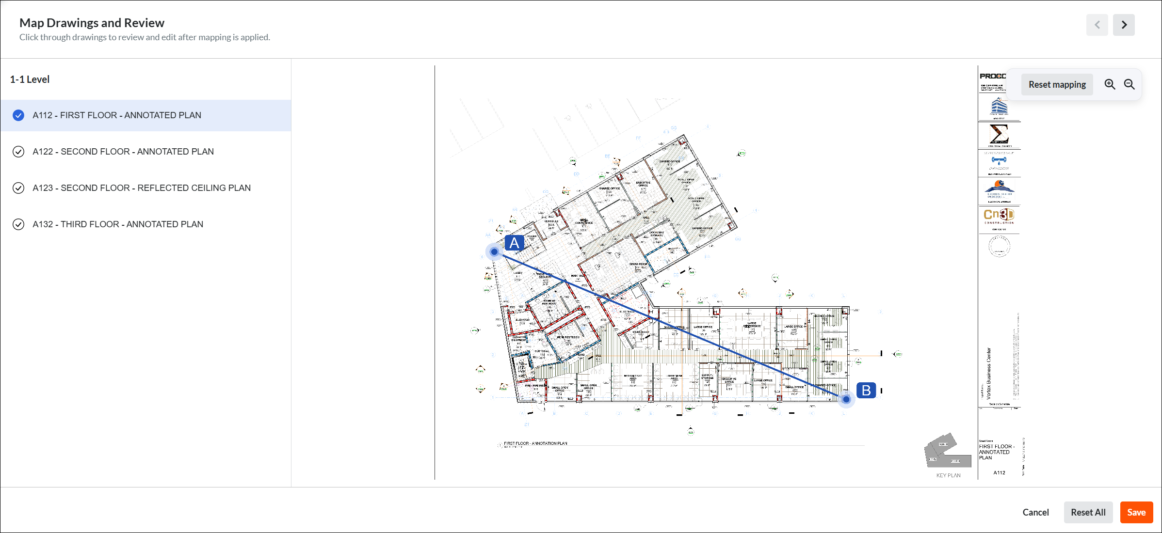
To clear your selected points, click Reset All.
To clear the selected points on one drawing, select the drawing and click Reset Mapping.
Click Save to confirm the points.
Click Done Mapping when finished.
Click Save Changes.

Select Processing Method & Publish
Before clicking Publish, choose how you want Procore to process your model data
Important
Use Section Boxes, Not Planes: To publish specific areas or views, ensure you Add a Section Box in Navisworks® before publishing. 'Section Planes' are not supported and will not be published in Procore.
Feature | Cloud Publishing (Recommended) | Local Publishing |
|---|---|---|
How to select | Clear the Publish Locally check box | Mark the Publish Locally checkbox |
Speed | Faster. Procore's servers handle the heavy lifting. | Slower. Uses your computer's CPU/RAM |
Multitasking | High. Continue working in Navisworks® or other apps. | Low. Your computer’s performance may be impacted. |
Best For | Standard NWD/NWF files and large project updates | Troubleshooting on publishing "locked" files. |
Export Grids from Autodesk® Revit®
Once you publish your model, you can use the Procore BIM Plugin to export the grids from Autodesk® Revit®. For the full tutorial, see Export Grids from Autodesk® Revit® to a Model in Procore.
To learn how, click Show / Hide Steps
The Navisworks® API cannot publish grid lines to Procore. To address this, use the Procore BIM Plugin to export them from Revit® instead. A team member must then verify that the coordinates align. Field teams rely on these accurate grid lines for precise installation.
Open the Revit® model that contains the grid line you want to export. Typically, this is an Architectural or Structural model.
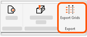
In Revit®, click the Procore tab to use the Procore BIM Plugin.
In the ribbon, click Export Grids.
In the Export Grids page:
Confirm that the Procore Company and Project are correct.
Under Coordinate System, select Internal or Shared.
Important
To prevent misalignment in the 2D View, the Coordinate System selected in the Procore BIM Plugin during the export must match the coordinate system used when the 3D model was published to Procore. See Why aren't my grids aligned in the Models tool?

Under Export To:
Find the correct Model Name.
Click Add Grids.
When successful, a checkmark and an Added message appears where the button once did.
Tip
Where can you view your exported grids? Exported grids assist viewers with on-site orientation, so they are only visible in the Procore for Mobile app. Grids do not appear in the Procore web application.
To confirm the grids were successfully exported:
Open the Procore for Mobile app.
Navigate to the Models tool.
Locate the model's card. A grid icon appears in the bottom left corner of the card, indicating that grids are available for the model.